
반응형
Notice
Recent Posts
Recent Comments
Link
| 일 | 월 | 화 | 수 | 목 | 금 | 토 |
|---|---|---|---|---|---|---|
| 1 | 2 | 3 | ||||
| 4 | 5 | 6 | 7 | 8 | 9 | 10 |
| 11 | 12 | 13 | 14 | 15 | 16 | 17 |
| 18 | 19 | 20 | 21 | 22 | 23 | 24 |
| 25 | 26 | 27 | 28 | 29 | 30 | 31 |
Tags
- healthy winter snacks for warmth
- definition and types of pumps
- features of different pump types
- foods that boost body temperature
- pump classification criteria
- plant operation and maintenance documentation
- honey for better circulation
- types of industrial pumps
- warm-up foods for winter
- natural remedies for cold hands and feet
- vendor data requirement (vdr) review
- health benefits of chives
- pump design standards
- centrifugal pump working principle
- difference between dynamic pumps and positive displacement pumps
- environmentally friendly power plant
- walnuts for winter health
- piping design standards
- managing vendor print schedule in engineering projects
- pump operation methods
- pump applications and case studies
- tbe report preparation guide
- piping stress analysis
- radish for improving circulation
- equipment data sheet and technical specifications
- ginger tea to raise body temperature
- design progress management
- key steps in vendor selection for epc contractors
- api standard pumps
- how to prevent colds with food
Archives
- Today
- Total
Safety Balance
Overview and Purpose of Piping Stress Analysis 본문
반응형
▣ Piping Stress Analysis
- Numerically verifies the design safety of piping systems, ensuring compliance with design codes and regulations, and determines whether the layout, support locations, types, and design requirements are met.
- Demonstrates numerically whether the system can be safely used within the allowable stress range under various loading conditions, as required by design specifications or standards, until the design life is reached.
- In piping systems that transport high-temperature fluids, the stress caused by thermal loads must be within the specified limits, and the layout must provide sufficient flexibility.
- It is appropriate to design not only for static conditions such as self-weight and thermal loads but also to ensure the integrity of the piping under dynamic conditions such as earthquakes and wind, ensuring economic operation.
- Stress analysis tasks should be performed using mathematical models for load conditions or boundary conditions. However, due to the complexity of the calculation process, numerical analysis using computer programs is employed to verify the displacements and integrity of the piping under load conditions through modeling techniques that closely resemble actual operating conditions.
▣ Summary of Stress Analysis Tasks
- Detailed stress analysis for verifying integrity.
- Review whether it meets the plant's characteristics or site design requirements.
- Evaluate the safety of piping under loads such as pressure, thermal expansion, self-weight, wind, and earthquakes.
- Examine whether the equipment nozzles connected to the piping are subjected to excessive loads.
- Select the appropriate location and type for pipe supports and pipe restraints.
- Review whether there is any interference with structures or other piping due to thermal expansion or vibration.
- Adopt scientific methods to achieve optimization rather than relying on excessive design based on experience.
- Numerically verify the safety of the piping system and ensure compliance with relevant design codes for analysis.
▣ Purpose of Stress Analysis
- Stress Analysis Standards (Reference Standards) and Analysis Criteria
- Apply the ASME B & PV Code, Section I, ASME B31.1, or B31.3; other matters follow the design criteria.
- Piping systems are classified as critical or general based on fluid energy density and system importance.
- Critical piping systems that require stress analysis.
- Critical Piping Systems in Power Plants
- Main Steam System
- Boiler Feedwater System
- Heater Drain System
- Extraction Steam System
- Condensate System
- Piping systems with a design temperature above 400°C and ANSI 900 lbs or higher.
▣ Essential Targets for Stress Analysis
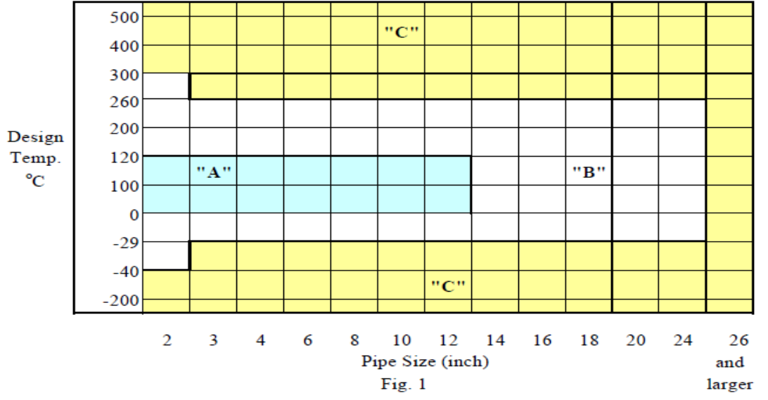
A) Piping systems where general analysis can be excluded.
B) Piping systems that can be approximately analyzed using simple calculations or graphics.
C) Piping systems that require detailed review using specialized analysis programs.
- Main Targets for Analysis Review in Power and Chemical Plants
- Inlet & Outlet piping for Turbines
- Inlet & Outlet piping for Compressors and Blowers
- Suction & Discharge piping for Process Pumps
- Inlet & Outlet piping for Air Fin Coolers
- Piping related to Fired Heaters
- Piping related to Reactors and Regenerators
- Jacketed piping
- Main Targets for Analysis Review in Power and Chemical Plants
- Piping with high risk due to flange leakage
- Piping handling hazardous materials classified as Fluid "M" Service
- Major piping classified as high pressure (1500# or higher)
- Piping requiring regulatory approval
- Non-metallic piping used in major processes
- Piping connected to Tanks or Vessels with significant settlement
- Piping expected to encounter two-phase flow or impact loads
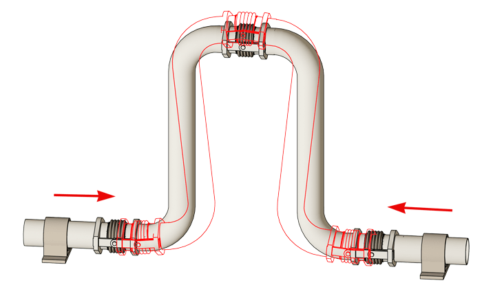
- Piping with Expansion Joints installed.
▣ Relevant Data Required for Stress Analysis
- Process Flow Diagram (PFD)
- Refer to temperature, pressure, flow rate, etc.
- Piping and Instrumentation Diagram (P&ID)
- Determine pipe size and insulation thickness.
- Piping Material Specification (PMS)
- Determine pipe size and insulation thickness.
- Equipment Drawing
- Review the location of connected equipment.
- Steel Structure Drawings
- Verify the location, height, direction, and size of structural members for pipe restraint.
- Piping Arrangement
- Determine the location, height, direction, and spacing of pipes.
- 3D Piping Analysis Model
- Must include support points and be used for computer input.
반응형
'Technical' 카테고리의 다른 글
| Plant Construction Business and Mechanical Design (0) | 2024.08.21 |
|---|---|
| Piping Stress Analysis Methods and Applications (0) | 2024.08.20 |
| "Standards Applied in Piping Design" (0) | 2024.08.06 |
| Piping Stress Analysis (0) | 2024.08.06 |
| Method for Writing Piping Design Documents (0) | 2024.08.02 |
'Technical' Related Articles
more


